
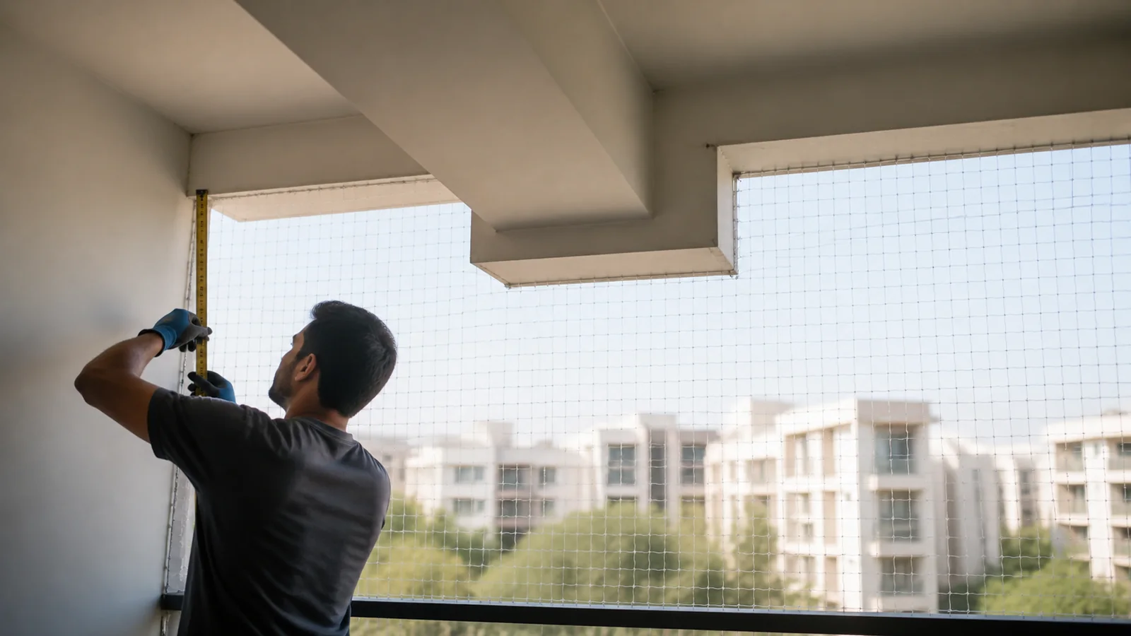
A balcony ceiling is not always one flat fixing line. A beam may drop across part of the opening, a soffit may step near a wall, or boxed services may create a recess and return. Measuring only the greatest width and height can produce a panel outline that ignores inside corners, depth changes and different substrates. The survey should segment the top boundary, use one datum, record every change point in elevation and section, and leave the installer responsible for confirming what can actually support the selected edge and fixing method.
Start With One Shared Datum
Choose a horizontal datum such as the finished floor line or another stable project reference. Assign a zero point at a named side wall or column. Measure every beam, soffit and corner from those references rather than creating independent dimensions that cannot be reconciled.
Record whether finishes are complete. Suspended panels, cladding or later ceiling work can change the visible edge without changing the structural background. Mark concealed conditions as unknown.
Divide the Top Edge Into Segments
Label each straight run T1, T2, T3 and so on. Record segment length, height above datum, depth or plane, visible material, corner type and photo ID. Show whether a transition is vertical, angled, curved or hidden behind trim.
Never average two ceiling heights. The panel and edge path must respond to the actual change, and the supplier needs to know where that change occurs along the width.
Add Sections for Changes in Depth
An elevation can show a dropped beam but not whether its face sits forward or behind the adjacent soffit. Draw a side section at each depth change. Record the underside, front face, recess, wall return and any gap that is visible from inside.
If the net plane is not yet chosen, show several architectural planes and let the installer propose the boundary. A dimension to the wrong plane can look precise while describing an unusable route.
Document Every Inside Corner
Inside corners around beams are easy to hide in wide photographs. Take square close-ups with the corner ID and adjacent segments visible. Record small steps, trim, pipes, lights, tracks, drainage, movement joints and access panels.
Never cover a service opening or assume it can be fixed through. Ask the building and installer teams which elements need access and which visible surfaces are structural, decorative or unknown.
| Top-Edge Field | Record | Common Ambiguity Removed |
|---|---|---|
| Segment ID | Start/end coordinates | Which run a length describes |
| Height | Value from shared datum | Maximum versus local height |
| Depth plane | Offset from proposed net plane | Front face versus recess |
| Corner | Inside/outside, angle, photo | Hidden return geometry |
| Substrate note | Visible material and uncertainty | Finish versus approved fixing base |
Ask How the Panel and Edge Will Follow the Shape
The supplier may propose one shaped panel, several panels, a seam, or another documented arrangement depending on geometry, material, edge finish and installation method. Use cut-panel identification so every piece and orientation remains traceable.
The buyer should not improvise deductions or seam positions. Ask for a returned drawing that shows the top outline, panel IDs, edge path and unresolved site confirmation points.
Check Material and Handling Implications
A transparent nylon net and a wire-reinforced cat net differ in construction and handling, but neither removes the need for continuous geometry. Discuss material preference, edge finish, panel size, visibility and installer method after the segmented boundary is known.
Avoid absolute safety language. The completed system depends on accurate product, edge, fixing, substrate, installation, use and inspection.
Control Revision After Ceiling Work
Ceiling finishes, lighting, facade work or service changes may occur after the first survey. Assign a survey revision and date. Before cutting, compare the current site with segment coordinates and photographs. If a beam face, soffit, trim or service box changed, issue a new drawing rather than annotating an old print informally.
At handover, photograph each completed corner and segment. Keep the as-installed record for future inspection or replacement without claiming the record itself guarantees performance.
Translate the Segmented Survey Into an Installer Walkdown
Print or display the segmented top-edge drawing at the balcony and walk from the named zero point through every segment. At each transition, call out segment ID, height, depth plane, corner photo and visible substrate. The installer should mark verified, changed, inaccessible or clarification required. A continuous walkdown is more reliable than checking isolated dimensions because it reveals whether two individually correct segments connect in the intended order.
Use temporary non-damaging site markers only when the building and installer procedure permits them. Never mark glass, facade finishes or services casually. If the proposed net plane moves forward or backward around a beam, add that route to the section drawing and reconsider panel division, edge length and access.
Close the walkdown with one annotated revision and a photo sequence in the same left-to-right order as the drawing. Remove superseded sketches from production and installer packs. During handover, repeat the segment IDs in completed-edge photos so later inspection can find the exact beam corner or soffit return without reconstructing the survey.
Give Every Top-Edge Change a Handover Reference
The completed record should connect segment IDs with panel, edge and installation photographs. Name the beam face, soffit return or recess rather than using photo numbers alone. Any inaccessible corner or approved limitation needs an owner and future inspection note. The building manager can then locate the exact top-edge detail without assuming that one wide balcony photograph proves boundary continuity.
Check for Repeating Geometry Before Standardizing Panels
In multi-unit buildings, two balconies may appear to share the same beam and soffit pattern. Compare segment coordinates, depth sections, finishes, services and verified substrates opening by opening before creating a standard panel family. Record which dimensions are common and which remain unit-specific. If standardization is approved, retain an opening schedule and field-verification gates. Never copy a shaped panel because the apartment plan name matches. Small facade or fit-out differences near an inside corner can change the top edge even when the broad elevation looks identical. Link every standardized panel family to the verified openings it actually covers and withdraw that status when later site work changes one member of the group.
Buyer Checklist
- Use one horizontal datum and named zero point.
- Label every straight top-edge segment.
- Record height and depth at each change.
- Photograph inside corners and interruptions closely.
- Separate visible finish from confirmed fixing substrate.
- Request a returned panel and edge drawing.
- Repeat verification after ceiling or facade changes.
Frequently Asked Questions
Can the highest ceiling value be used for the whole opening?
No. Record every local height and the exact position where the top boundary changes.
Should buyers deduct for a beam?
Provide measured geometry; the supplier and installer should define panel and edge allowances for the selected method.
Can one panel follow several steps?
It may be possible for some designs, but the decision depends on actual geometry, material, edge treatment and installer method.
Related Product or Reading
For lower-edge and post geometry, combine this method with the handrail-to-ceiling boundary survey.
Discuss the Exact Project
Send MaxCatNet the datum drawing, segmented elevation, depth sections, corner photos, substrate notes, service openings, material preference, and installer confirmation points.